Facebook twitter p linkedin youtube ins
Engineering
Home |

Engineering

Product Design/  Mold Innovation/  Moldflow Analysis

  • Innovation
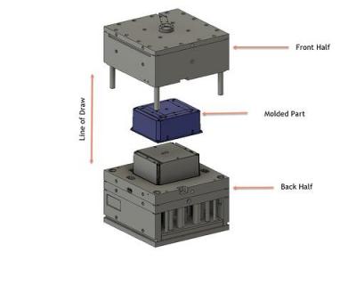
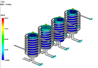
    What's the Mold Design Mold Design refers to design a mold that is suitable for manufacturing a product based on the shape and requirements, in order to facilitate processing processes such as injection molding , die-casting and stamping. General Steps for Mold Design: Product Analysis: Analyze the product to be manufactured, understand the shape,size, materials and manufacturing requirements ,and determine the type of mold required (injection mold, die-casting mold and stamping mold) Mold layout:Determine the overall structure and layout of the mold based on the shape of the product and manufacturing process requirements. it includes determining the parting method of the mold, number of mold cavities ,runner system, guiding system, cooling system. Mold size Design: Determine the geometric dimensions of the mold based on the size requirements of the product. it includes mold insert and moldbase dimessions,guide component dimensions. At the same time, appropriate corrections and calculations should be made based on factors sush as material shrinkage. Component Design: For large mold, it is also necessary to design and determine the size and structure of each component, such as the moldbase, guide pillar, guide pin, pull rod and ejector pin. Mold material Selection: Select appropriate materials based on the usage requirements and environment of mold. Common mold materials include stell and thermosetting materials. Mold manufacturing process Selection :Select suitable mold manufacturing process ,including CNC machining , Electric discharge machining, Wire cutting machining. Mold performance Verification: By simulation injection molding or die-casting processes, the performance of the mold is verified and corrected to ensure stable and efficient production Some important factors before Mold-Design   Adding Draft  Angle     An injection molded part needs to come out of the mold without damage or too much resistance. To avoid these issues, you want to angle the walls of the part from the parting line (drafting). Generally speaking, there should not be any surface of the part that is exactly 90 degrees to the line of draw on the mold. Not drafting a part can cause defects like drag marks and create difficult ejection.     The amount of draft you should apply to the part depends on the application. The general rule is to have at least one degree for every inch of depth Avoiding Thick Areas      The thickest area of the molded part will determine the amount of cooling time. Cooling time often represents the longest part of the injection molding process. Longer cooling time makes a longer cycle time, which increases costs. Excessive wall thickness can also create part defects like sink marks and voids.  For most applications, excessive wall thickness is larger than .125 - .1875 inches. Thick wall sections are moldable, but they open up the potential for part defects and long cycle times. Although there are certain materials and additives to achieve thick wall sections, it's best to start thin. Doing so reduces cycle time and saves on material usage, both of which save on the ongoing piece price.Design note: Having to "add plastic" to a molded part means removing steel from the mold. Machining away material in the mold is much cheaper and easier than welding and machining.    Added Coring    To avoid thick sections of a part, you can add coring and ribbing. These features reduce cycle time, reduce part weight, and could make the part stronger. Designing these features into the core side of the part is common and is the best practice. These features can help pull the part to the cavity side or ejection side of the mold; they would then be on the non-show side of the part. However, it's possible to have them on the core side of the tooling as well.    The left image  shows a perfect example of coring a part. Since this part required one large wall section, you can remove large sections of material without sacrificing strength. Added Ribbing   Adding ribs is a great way to add significant strength to a part without affecting cycle time. Ribs can also reduce the amount of material that is used in the part.   The right image  shows a boss before and after adding support ribs. Since these ribs are thin, they do not increase cooling time, but they do add strength.               Surface Finish Building injection molds requires several different pieces of equipment. To create molding surfaces, they may be CNC machined, ground, EDM, turned, and so on. Each of these manufacturing processes will generate different surface textures. These textures (tooling marks) may be acceptable for non-show surfaces, but in many cases, tooling marks need to be smoothed out or textured. Creating a texture not only makes the surface of the molded part consistent, but it also has implications on part...

    Hot Tags : injection mold innovation Die casting mold innovation metal stampe mold innovation 
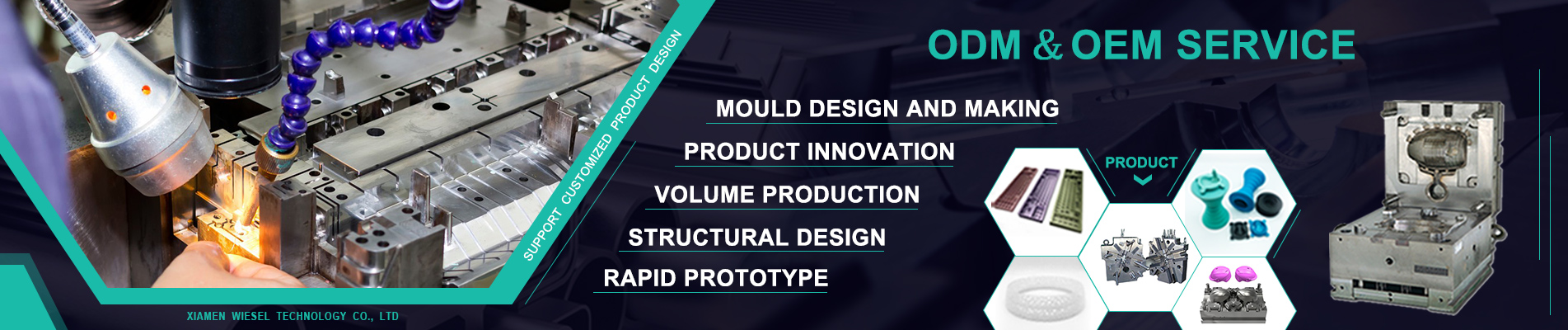
OEM/ODM Product innovation

    Read More
  • Moldflow
    Why need to do Mold CAE Before mold Production? In today’s mold design process, CAE technology is more and more important, before that, Our designers cannot ensure that their design is completely correct, Process simulation is the core of CAE technology. because Simulation of both the induction heating and injection molding processes optimizes cycle time and final part results. What's the Moldflow for plastic product? Plastic Moldflow Analysis refers to the simulation and analysis of the flow channels, nozzles,injection process through moldflow analysis software ,in order to detemine the optimal injection molding parameters and optimize the mold structure,thereby improving the quality and production efficiency of injection molded parts.  Moldflow analysis can effectively evaluate the fluidity,filling ability, compressibility and other properties of plastic when injection. Moldflow can identify flowtime,bubble, warpage and other defects in advance and optimize the injection process parameters and mold design to ensure the stable molding quality of injection molding parts. Fill/Pack Analysis Manufacturing a quality product starts with an optimized filling and packing stage. Fill/Pack analysis allows the designer to see the resin behavior in the mold and determine the process parameters required to fill the part. The Madison Group can provide the following information from performing a fill and pack analysis: Runner/gate sizing Tonnage requirements Weld line placement Molding optimization Gas trap locations Material selection Sink marks Gate positioning Molded-in stresses Pressure requirement Cooling Analysis (Steady State And Transient Analysis) > Cycle time optimization  > Transient cooling analysis   > Optimized coolant conditions  > Conformal vs traditional cooling line comparison  > Selection of high-conductivity inserts  > Effect on warpage  > Evaluation of baffles and bubblers  > Circuit pressure drops Warp Analysis Designers use injection molding to mass produce high precision intricate parts. After designing the part it is important to ensure the part can be manufactured within tolerance and will not exhibit excessive warp. Warp is related to several factors including part design, resin selection, fiber orientation, the molding process, or cooling system. Performing a warp analysis helps isolate the reasons for part distortion after molding and creates a solid foundation for making changes to reduce or eliminate the distortion. Using warp analyses can assist in identifying design and process variations that cause warp, conduct material comparison, and find solutions to ensure the manufacturing quality parts Metal Forming Simulation In metal forming simulation, the forming of sheet metal is simulated on the computer with the help of special software. Simulation makes it possible to detect errors and problems, such as wrinkles or splits in parts, on the computer at an early stage in forming. In this way, it is not necessary to produce real tools to run practical tests. Forming simulation has become established in the automotive industry since it is used to develop and optimize every sheet metal part. To illustrate the metal forming process, there must be a model of the real process. This is calculated in the software using the finite element method based on implicit or explicit incremental techniques. The parameters of the model must describe the real process as accurately as possible so that the results of the simulation are realistic.

    Hot Tags : plastic product moldflow injection plastic part moldflow OEM/ODM product moldflow plastic product moldflow service Free moldflow service

    Read More
  • Product Design
    Product design as a verb is to create a new product to be sold by a business to its customers. A very broad coefficient and effective generation and development of ideas through a process that leads to new products. Thus, it is a major aspect of new product development. Why need to make the product Innovation before production,some structure isn't suitability for production,Not suitability material can't meet product need, Not right surface finish can't meet the customer need, if can solve them before production can save the time and money What can we do for you? Optimization of Structural Product Some products are not suitability for production that the structure is too complex and adds the cost when production. When we get any projects, Wiesel will make suggestions and modify drawing by fee for customer. Some main Factors: -Not Appropriate Wall-thickness - Wrong Drawing Angle  -Not Ringh Snap  for assemble - Not Right Angle for Texture Product Layout-2D Drawing Some customers only have the 3D drawing or 2D drawing,but they want to produce and need a ful drawing after finishing the project. Wiesel will have the free service for each project. - Drawing 3D follow 2D drawing - Drawing 2D follow 3D drawing -Scan the sample and make the 3D drawing   Design for Manufacturing  Before Production,Wiesel will make a report of DFM for product if the project needs to modify the design. •Angle for CNC •Choose the type of Texture •Choose the best fillet for CNC or Molding •Choose the best material for each part MoldFlow Analysis For Plastic and Metal Product Before Each Project, Wiesel will send a report about Moldflow that don't Need add extra Fee. Generally, Report include the below points: --Best Gating Position --Flow Time --Pressure when Flow -- Welding line and Gas Trap loaction    

    Hot Tags : product design service plastic product design metal product design OEM/ODM product design Product desing company in china medical equipment product design LED light product design OEM toys product design

    Read More
A total of1pages
leave a message
Leave A Message
If you have questions or suggestions,please leave us a message,we will reply you as soon as we can!

Home

Products

whatsapp

contact